The description of V-switch and principles of its work.
As a key of commutation of current in a coil I use a usual silicon-controlled rectifier (SCR). It has some advantages compared to MOSFET, IGBT and other power semiconductors. They are low price, small size, a huge overload power, one more advantage is that a big amount of power can be switched or controlled using a small triggering current or voltage. A small SCR intended for direct current 25 amps by a short impulse continuing 10 ms can sustain a current up to 350 amps. In the coil the impulse is even shorter – a bit more than 1 ms and the current 400 amps doesn’t cause destruction of SCR. The main drawback of SCR is impossibility of switching it off by means of control electrode. I obviate this difficulty with the help of a specially designed scheme V-switch. Compared to the usual scheme with a capacitor and SCR, the scheme V-switch is supplied with one smaller capacitor and SCR. Additional capacity is chosen approximately from 1/15 till 1/10 value of the main capacitor. I use equal thyristors: intended for direct current 25 amps and voltage 1400 volts. In the initial state the main capacitor 600 uF and additional one 47 uF are charged till the equal voltage +800 volts. In the moment of a shot the trigger mechanism slightly pushes the projectile in the coil, and the switcher of the shot sends the operating impulse to the main SCR through pulsing transformer. Pulsing transformer is ideally suitable for application in a coilgun, as it has low resistance and protects SCR from false actions. The thyristor turns-on, and current in the coil starts to grow smooth, as usual. I select an inductance of the coil the way that by the moment when the projectile is pulled fully into the coil the current already achieves the maximum and starts slowly falling down. By that moment the voltage in the main capacitor is reduced till around +300 volts. |
|
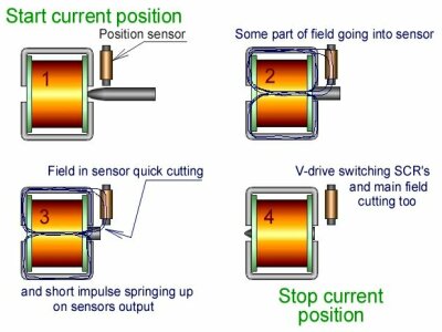
In the usual scheme the current keeps falling down slowly (as it is shown by red dotted line in the diagram at the bottom of the picture). Magnetic field doesn’t have time to stop and doesn’t let the projectile fly out from the coil - and a "suck-back effect" appears. V-switch works in a different way. V-switch has an inductive sensor for the purpose of controlling the position of the projectile. In the moment of a shot the magnetic field of the main coil partly penetrates into the core of the sensor because the projectile closes the area of magnetic way. Just before the moment when the projectile pulling completely into the coil the end of the projectile passes by the sensor, the magnetic field in the core stops abruptly , and this causes the impulse of the current in the sensors output. |
 This impulse will open an additional SCR and an additional capacitor
will be connected up to the coil, while it is not yet completely discharged.
Moreover the capacitor has small capacity that’s why it discharges very
quickly but during the time of its discharging the main SCR closes. It
is achieved due to the difference in voltage between the discharged main
capacitor and an extra capacitor that only starts discharging.
This impulse will open an additional SCR and an additional capacitor
will be connected up to the coil, while it is not yet completely discharged.
Moreover the capacitor has small capacity that’s why it discharges very
quickly but during the time of its discharging the main SCR closes. It
is achieved due to the difference in voltage between the discharged main
capacitor and an extra capacitor that only starts discharging.
Not every thyristor is suitable for work in the scheme V-switch. Consult reference data for choosing a thyristor with small restriction "circuit commutated turn-off time". I use thyristors with a turn-off time 0,07ms or quickly. It’s quiet a good parameter circuit commutated turn-off time for a high-powered thyristor. A typical turn off time of 0,07ms is specified for standard gate thyristors and 0,1ms for sensitive gate thyristors. Thyristors possessing a turn-off time from 0,1ms and more are not applicable for the scheme V-switch. So, the main thyristor has closed in time and the additional one is opened and a small extra capacitor discharges rapidly. The abruptly stopped current in the coil causes a reverse charge of an extra capacitor with a negative charge up to –1000 volts and even –1200 volts. The negative charge can be even more, but it is slightly hindered from the acting of protect bypass diode, which is connected up parallel to the coil. A resistor 15R 2W is attached to the diode consecutively. Diode prevents the work of the V-switch, but the output of negative charge would be too high without it. Resistor 15R – is a compromise. In this case the off-state breakdown voltage of both thyristors should certainly exceed 1200V. |
 Now in the work of the V-switch comes the most dramatic point: the capacitor,
that is intended for a positive charge of 800 volts, has a negative charge
of -1200 volts.
If nothing is done you will become a lucky eye witness of the electrolytic
capacitor’s explosion. I haven’t seen such an explosion, but they say it is
impressive.
Now in the work of the V-switch comes the most dramatic point: the capacitor,
that is intended for a positive charge of 800 volts, has a negative charge
of -1200 volts.
If nothing is done you will become a lucky eye witness of the electrolytic
capacitor’s explosion. I haven’t seen such an explosion, but they say it is
impressive.
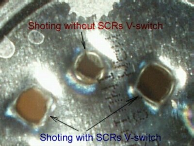
Capacitor doesn’t explode for two reasons: first, it starts discharging very quickly at once through the resistor 300R 1W. Second, till the moment of the critical impulse, the capacitor has been charged over a long period of time up to +800 volts, and the electrolytic dielectric surface on its facing on foil areas acquires sufficient firmness. Then DC/DC converter charges both capacitors again up to +800 volts and the V-switch is ready for the next shot. Effectiveness of such current control is shown on the picture – a projectile comes throughout the bottom of the tin by the turned-on V-switch, and stays outside by the turned-off V-switch, though it makes a hollow with a small aperture. |
(C) Evgenij Vasiljev, June 2003.
Mail: